




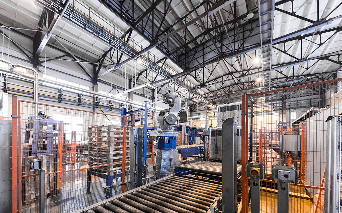
HVAC System Design for Multi-Product Manufacturing Facilities
Designing an HVAC system for a multi-product manufacturing facility is not simply a matter of calculating cooling loads, selecting air handling units, and arranging ductwork. It is the process of developing an environmental control system capable of supporting multiple production processes, different material characteristics, and varying risk levels within the same facility.
- 1. What Is HVAC System Design for a Multi-Product Manufacturing Facility?
- 2. Why Does a Multi-Product Facility Need a Dedicated HVAC Strategy?
- 3. Establishing the Design Basis and HVAC User Requirement Specification
- 4. Product Risk Assessment and Facility Zoning
- 5. Cross-Contamination Control in Multi-Product Facilities
- 6. Designing Pressure Cascades and Airflow Direction
- 7. Selecting AHU Configurations for a Multi-Product Facility
- 8. Controlling Temperature, Humidity, Cleanliness, and Air Changes
- 9. Supply-Air, Return-Air, Exhaust, and Dust-Extraction Design
- 10. HVAC Control, Monitoring, and Alarm Systems
- 11. HVAC Testing, Commissioning, and Qualification
- 12. Common HVAC Design Errors in Multi-Product Facilities
- 13. Criteria for Selecting a Cleanroom Equipment Supplier
- 14. FAQ: HVAC Design for Multi-Product Manufacturing Facilities
- 15. Conclusion
When the system is not designed appropriately, air can become a pathway for spreading dust, odors, solvent vapors, microorganisms, or active substances from one production area to another. The consequences may include cross-contamination, operator exposure, environmental impact, qualification failure, and interruptions to manufacturing operations.
For this reason, HVAC System Design for Multi-Product Manufacturing Facilities must be based on risk assessment, zoning strategy, personnel and material flows, product characteristics, and actual operating conditions. The objective is not to build the most complicated system, but to create a solution that is safe, stable, controllable, maintainable, and capable of demonstrating its performance through reliable data. Let's find out with VCR!
1. What Is HVAC System Design for a Multi-Product Manufacturing Facility?
HVAC stands for Heating, Ventilation and Air Conditioning. In a manufacturing facility, the HVAC system controls temperature, relative humidity, air cleanliness, room pressure differentials, airflow direction, and ventilation rates.
In a conventional industrial building, HVAC may mainly provide thermal comfort for personnel and suitable operating conditions for machinery. In pharmaceutical, cosmetic, food, medical device, electronics, and other controlled-environment facilities, however, HVAC is also an important part of the quality control system.
A multi-product manufacturing facility is a site that uses some or all of the same production rooms, equipment, utilities, personnel, and supporting systems to manufacture different products. These products may vary in dosage form, composition, dust generation, allergenic potential, toxicity, temperature sensitivity, humidity requirements, and required cleanliness classification.
For example, the same pharmaceutical facility may manufacture tablets, capsules, powders, and liquid products. A cosmetics plant may manufacture creams, solutions, shampoos, and alcohol-based products. A food facility may handle powdered materials, liquids, flavoring agents, and allergenic ingredients within the same building.
In these situations, HVAC design must answer several critical questions. Can air from a room manufacturing Product A be returned to an air handling unit and then supplied to a room manufacturing Product B? Should a dispensing room operate under negative or positive pressure? How should the air system be cleaned or controlled during product changeover? Can the operation of a Passbox or an opened door disturb the intended airflow direction?
HVAC design for a multi-product facility is therefore the process of identifying and controlling all airborne contamination pathways. The system must protect the product from the surrounding environment, protect operators from exposure to the product, and prevent one product from adversely affecting another.
2. Why Does a Multi-Product Facility Need a Dedicated HVAC Strategy?
Each product has different physical, chemical, and microbiological characteristics. One material may be highly hygroscopic, while another may generate substantial airborne dust. One process may require positive pressure to protect the product, while another may require negative pressure to prevent hazardous material from escaping the room.
If every production area is designed using the same HVAC configuration, the system may be suitable for one product but create risks for another. A multi-product facility therefore requires an HVAC strategy based on the characteristics and risks of each product group and production stage.
Cross-contamination is usually the most significant concern. Dust or vapors generated in one room can move through door gaps, return-air systems, corridors, ceiling voids, or shared extraction systems and contaminate another room. This risk is particularly important for highly active compounds, allergens, odorous materials, toxic substances, or products with low occupational exposure limits.
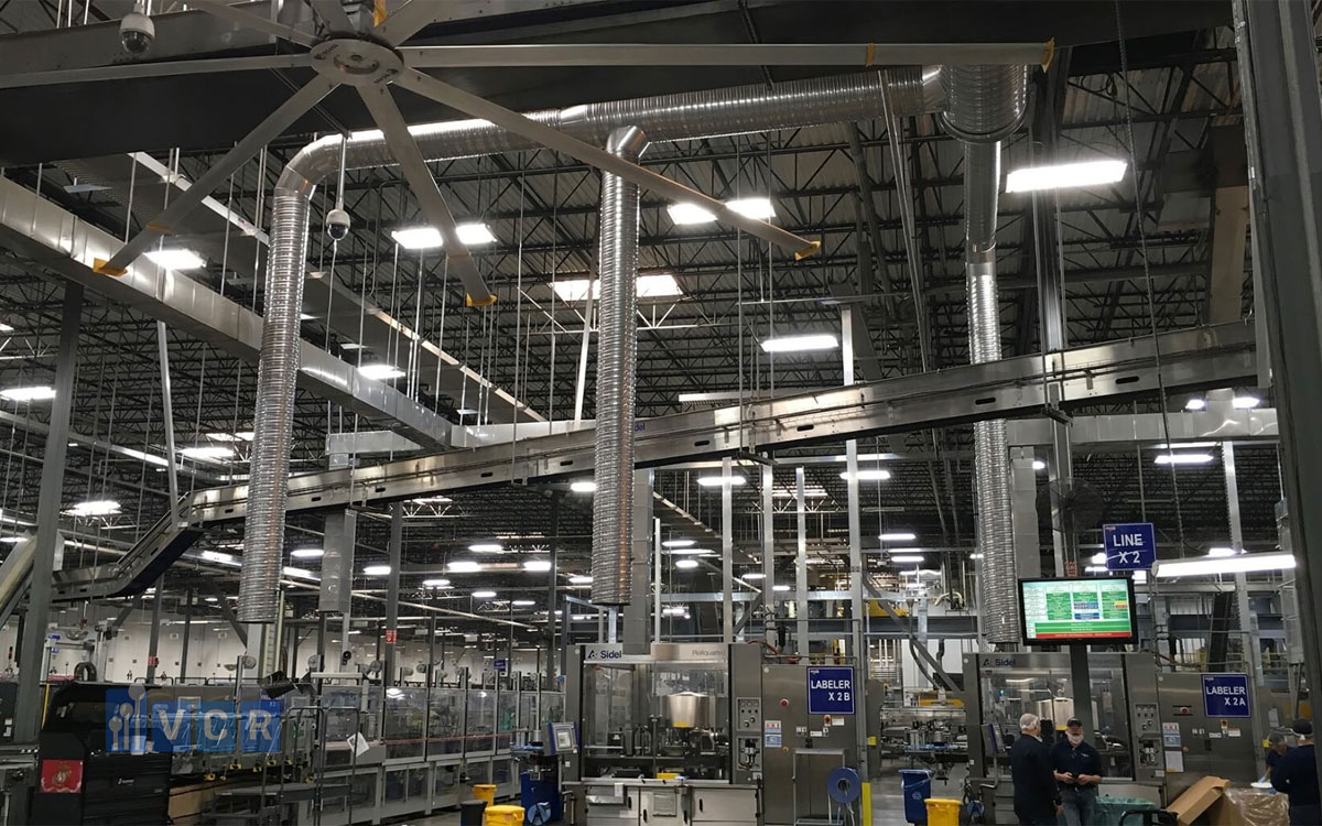
Read more: How to prevent cross-contamination in cleanroom?
Another challenge is the variation in operating conditions. When production changes from one product to another, the number of operators, equipment heat load, humidity requirement, and quantity of dust generated may change significantly. If the HVAC system is designed for only one fixed operating condition, it may become unstable when a different product is manufactured.
A dedicated HVAC strategy also supports cost optimization. Not every room requires terminal HEPA filtration, a high air-change rate, or a 100% fresh-air system. At the same time, using one AHU for incompatible production areas merely to reduce initial capital cost may create unacceptable contamination risks.
A well-designed system should balance risk control with energy efficiency. Compatible rooms can be grouped to reduce the number of AHUs and ductwork systems. Higher-risk zones should be separated, even when this increases the initial investment.
Campaign manufacturing, in which one product or one compatible product family is produced during a defined period, does not automatically eliminate cross-contamination risk. Residual dust may remain inside ductwork, filters, AHUs, dampers, or inaccessible surfaces after production has stopped.
The HVAC strategy must therefore support cleaning, product changeover, shutdown, restart, maintenance, and production scheduling. It should remain effective not only during normal production but also during transitional operating conditions.
3. Establishing the Design Basis and HVAC User Requirement Specification
Before selecting an AHU or calculating supply-air volume, the project team must establish a clear design basis. One of the most important documents is the URS, or User Requirement Specification.
The URS defines what the HVAC system is required to achieve without necessarily specifying every detail of how the system must be manufactured or installed. It creates a common technical reference for the owner, consultant, HVAC contractor, cleanroom contractor, equipment supplier, validation team, and quality department.
The first requirement is a complete product list. Each product should be evaluated according to its physical form, composition, dust-generation potential, sensitivity to temperature and humidity, microbiological control requirements, toxicity, allergenic potential, odor, and likelihood of airborne dispersion.
The production process must also be understood in detail. The designer needs to know each process step, where the product is exposed to the room, where dust or vapor is generated, and which areas require washing, cleaning, or disinfection.
Designing HVAC only from room names can lead to serious mistakes. A room called a “mixing room” may involve a fully closed process in one factory but an open, dust-generating process in another. The resulting pressure regime and ventilation requirements may therefore be completely different.
Production equipment data is equally important. Machinery may generate heat, release moisture, extract room air, or discharge process air outdoors. A dust collector, fume hood, weighing booth, or extraction hood may substantially alter room air balance if its exhaust volume is not included in the HVAC calculation.
The URS should define the required environmental parameters, including temperature, relative humidity, cleanliness classification, room pressure differential, filtration level, and expected air-change rate. These values should not be copied directly from another facility. They must be established according to the product, process, risk assessment, and applicable regulatory standards.
For cleanrooms, ISO 14644 provides a widely used framework for cleanroom classification, testing, and monitoring. ISO 14644-1 addresses airborne particle classification, ISO 14644-2 covers monitoring related to air cleanliness performance, and ISO 14644-3 describes test methods for cleanrooms and controlled environments.
For sterile pharmaceutical manufacturing, EU GMP Annex 1 places strong emphasis on contamination control strategy and quality risk management. However, compliance with a standard does not replace the need to understand the specific process and contamination risks of the facility.
The URS should also define the required operating modes, such as normal production, standby, cleaning, maintenance, shutdown, power failure, and restart. A system that performs correctly only at full capacity but becomes unstable during low-load operation is not a robust design.
Future expansion should be considered. If additional rooms, production lines, or new products may be introduced, the system should include reasonable allowance for cooling capacity, airflow, fan static pressure, technical space, controls, and connection points.
The URS becomes the reference for tender evaluation, detailed design, manufacturing, Factory Acceptance Testing, Site Acceptance Testing, commissioning, and qualification.
FAT stands for Factory Acceptance Test, which is performed at the equipment manufacturer's facility before shipment. SAT stands for Site Acceptance Test, which is carried out after installation at the project site.
A clear URS reduces ambiguity, limits costly changes during construction, and provides objective criteria for system acceptance.
Read more: The differences between cleanroom HVAC system and other HVAC systems
4. Product Risk Assessment and Facility Zoning
HVAC design for a multi-product manufacturing facility must begin with risk assessment. The purpose is to identify which materials, products, and process stages may affect other areas and determine whether that risk is acceptable.
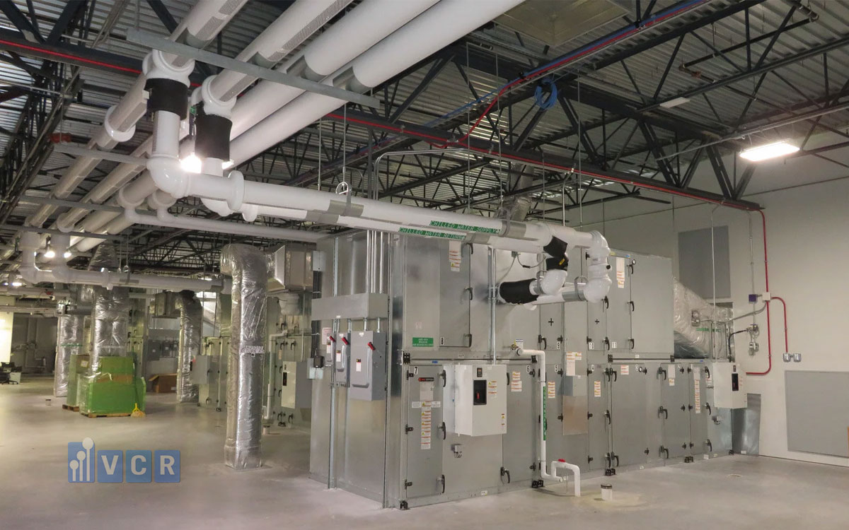
QRM stands for Quality Risk Management. It provides a structured approach for making decisions based on hazard, probability, detectability, and available scientific evidence rather than relying solely on past experience.
Factors that should be evaluated include toxicity, allergenic potential, pharmacological activity, particle size, volatility, odor, persistence, cleanability, and occupational exposure limits. Products with very low exposure limits generally require stronger containment controls.
Open-product operations deserve particular attention. While products remain inside closed processing equipment, their airborne dispersion risk is usually lower. The risk increases during sampling, dispensing, charging, unloading, transfer, equipment opening, and cleaning.
Based on the assessment, the plant can be divided into zones according to cleanliness classification, pressure regime, temperature, humidity, contamination hazard, or product family. Zoning should not be based only on room names or departmental ownership.
Layout planning must be developed together with the HVAC strategy. Personnel flow, raw material flow, finished-product flow, waste flow, and equipment movement should be arranged to minimize crossing and backtracking.
A poor layout cannot always be corrected by adding more air changes or stronger pressure differentials. Architectural zoning and HVAC zoning must support each other.
Dispensing rooms often generate dust and may need to operate at a lower pressure than adjacent spaces. However, if the raw material must also be protected from environmental contamination, the design must satisfy both objectives: protecting the product and preventing dust from escaping.
Liquid-processing rooms may generate heat, moisture, odors, or solvent vapors. Primary packaging areas may have different risks from secondary packaging areas. Warehouses storing hygroscopic raw materials may need tighter humidity control than standard production rooms.
A common mistake is grouping all rooms with the same cleanliness classification under one AHU. Cleanliness grade represents only one part of the requirement. Two rooms with the same ISO Class may manufacture incompatible products, require different pressure regimes, or present different cross-contamination risks.
Zoning results should be clearly shown on the drawings. The layout should indicate room classification, pressure value, airflow direction, serving AHU, air-return strategy, exhaust requirements, and associated contamination-control equipment.
This information becomes the coordination basis for architecture, mechanical systems, electrical systems, controls, cleanroom panels, doors, and production equipment.
5. Cross-Contamination Control in Multi-Product Facilities
Cross-contamination is the unintended presence of one material, product, microorganism, or contaminant in another product. In a multi-product facility, HVAC can be an effective contamination-control measure, but it can also become a distribution pathway if poorly designed.
Airborne cross-contamination occurs when dust, aerosols, vapors, or microorganisms are carried by airflow. Contaminants may move through door openings, leakage paths, return-air ducts, ceiling spaces, common extraction systems, or improperly sealed penetrations.
The first control principle is to reduce contamination at the source. Increasing the overall room air-change rate is not always the most effective solution. Dust should be captured as close as possible to the dispensing, charging, discharging, or sampling point.
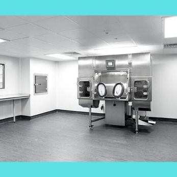
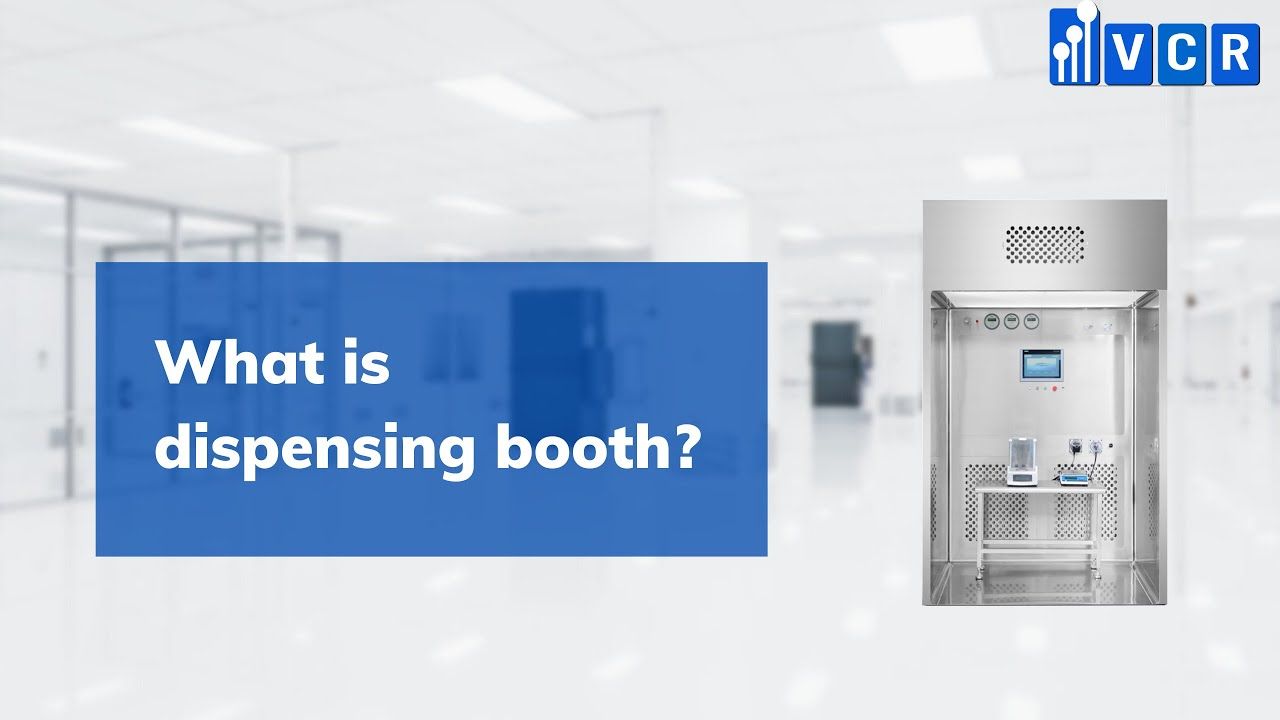
A Dispensing Booth, also known as a weighing booth, can create a controlled airflow pattern around the operator and capture airborne dust generated during weighing and material transfer.
A Sampling Booth provides a controlled environment for sampling raw materials. Local exhaust ventilation may also be connected directly to production equipment, but the extraction airflow must be included in the overall room air balance.
For higher-risk products, closed processing equipment, isolating technologies, or containment systems may provide better protection than increasing room ventilation alone. HVAC should not be expected to compensate for an inherently uncontrolled open process.
Return air requires careful consideration. In a recirculating system, a portion of room air is returned to the AHU, mixed with fresh air, treated, filtered, and supplied again.
This arrangement can improve energy efficiency, but it may also create a contamination pathway between rooms. Return air should only be used when the risk assessment demonstrates that contaminants are adequately controlled and the served areas are compatible.
For toxic compounds, allergens, highly active powders, strong odors, or solvent vapors, a 100% fresh-air and total-exhaust system may need to be considered.
However, 100% fresh-air systems require significantly higher cooling and dehumidification capacity, particularly in hot and humid climates such as Vietnam. The decision should therefore be based on technical analysis and risk assessment, rather than being selected automatically as the safest option.
Airlocks help maintain separation between zones. Different pressure configurations can be used depending on whether the priority is to protect the product, contain hazardous materials, or achieve both objectives.
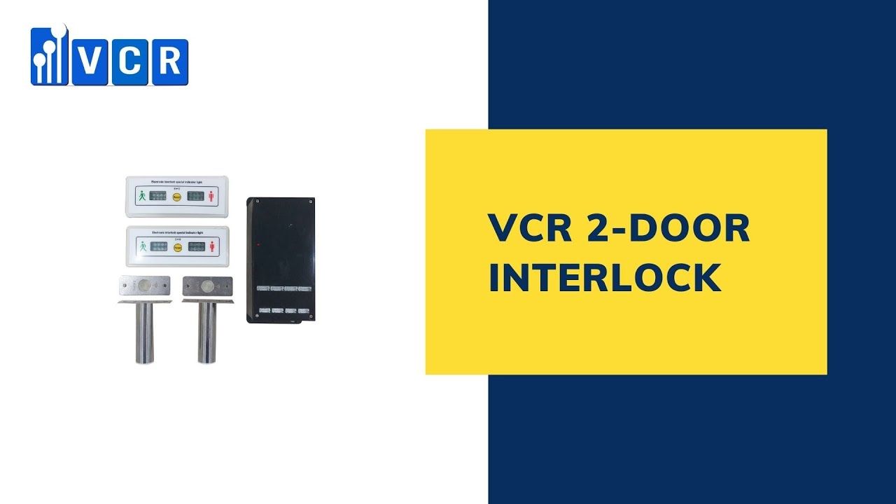
An interlock system prevents two airlock doors from being opened simultaneously. However, door interlocking cannot replace proper airflow calculation. If the room envelope is excessively leaky or the supply and extract volumes are not balanced, pressure control will remain unstable even when the doors operate correctly.
Campaign manufacturing requires a defined changeover procedure. The facility should establish the sequence for production shutdown, room cleaning, equipment cleaning, filter inspection, HVAC operation, and release before the next product is introduced.
Potential dust-retention points include return-air ducts, filter housings, dampers, internal AHU surfaces, and inaccessible duct sections. These areas should be included in the contamination-risk assessment.
The HVAC system should support the cleaning strategy rather than create surfaces that cannot be inspected or maintained. Access doors, filter housings, drain pans, and internal AHU sections should be arranged for practical inspection and servicing.
Where direct cleaning is not possible, the design should demonstrate that the residual contamination risk is controlled through filtration, dedicated systems, product grouping, or other appropriate measures.
6. Designing Pressure Cascades and Airflow Direction
A pressure cascade is a sequence of pressure differentials between adjacent rooms. When a door gap or leakage path exists, air generally moves from the room with higher pressure toward the room with lower pressure.
Where the objective is to protect the product from contamination in surrounding areas, the production room is often maintained at a positive pressure relative to adjacent spaces.
Where the objective is to contain dust, odors, toxic materials, or highly active substances, the room may be maintained at a negative pressure relative to the surrounding area.
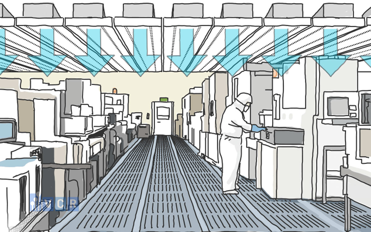
In a multi-product facility, higher pressure does not always mean cleaner or safer. A classified room handling a potent compound may still need to operate negatively relative to the corridor to prevent the substance from escaping.
An airlock can help resolve the conflict between product protection and containment. For example, the production room may be negative relative to the airlock, while the airlock arrangement prevents uncontrolled air from the general corridor from entering directly into the production area.
The pressure differential must be sufficient to establish a reliable airflow direction but should not be unnecessarily high. Excessive differential pressure can make doors difficult to open, create whistling noise through gaps, cause turbulence during door opening, and increase fan energy.
A single pressure value should not be copied across all projects. The appropriate differential depends on room airtightness, door leakage, opening frequency, airflow paths, operating modes, and the accuracy of the measuring instruments.
Room pressure is generated by the difference between supply air, return air, and exhaust air. A positive-pressure room usually receives more supply air than the combined return and exhaust flow. A negative-pressure room normally has more extracted or exhausted air than supplied air.
Room airtightness directly affects pressure stability. If cleanroom panels, ceilings, doors, electrical outlets, pipe penetrations, and service openings are not properly sealed, a larger offset airflow will be required to maintain the target pressure.
This increases energy consumption and may make pressure control difficult. Good envelope construction is therefore as important as fan capacity.
Door opening creates a much larger air exchange than normal leakage under closed-door conditions. The control system should not react excessively to every short pressure fluctuation.
If fan speed changes too rapidly whenever a door opens, the system may overshoot and continue oscillating after the door closes. Suitable control delay, averaging, and PID tuning are therefore necessary.
Differential pressure sensors should be installed away from direct supply-air jets, vibration sources, and locations prone to damage. Pressure tubing must be correctly connected, free from kinks and blockages, and protected from condensation or contamination.
A local differential pressure gauge allows operators to check room conditions immediately. Transmitters can send signals to the BMS or EMS for data logging, trending, and alarm generation.
Alarm logic should distinguish between brief pressure disturbances caused by door opening and sustained loss of control.
7. Selecting AHU Configurations for a Multi-Product Facility
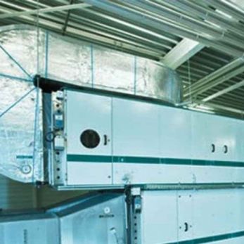
AHU stands for Air Handling Unit. It may perform functions such as filtration, cooling, heating, dehumidification, humidification, fresh-air introduction, and air recirculation.
The number of AHUs should not be determined only by the floor area. One AHU may serve several rooms when their temperature, humidity, classification, operating schedule, and product risks are compatible.
Separate AHUs may be required for areas with high cross-contamination risk, special humidity conditions, hazardous substances, or significantly different operating schedules.
Dedicated AHUs improve separation and operating flexibility, but they increase initial cost, plant-room space, controls, ductwork, and maintenance requirements.
A recirculating HVAC system returns part of the room air to the AHU. The air is mixed with outdoor air, filtered, cooled or heated, and supplied back to the rooms. This arrangement is generally more energy-efficient because the entire outdoor air volume does not need to be conditioned.
A 100% fresh-air system supplies only outdoor air and exhausts all room air. This configuration may be appropriate for solvent-handling rooms, odorous processes, hazardous compounds, or areas where air recirculation creates unacceptable contamination risk.
However, its cooling, heating, and dehumidification loads are substantially higher.
A mixed fresh-air and return-air system is commonly used. The fresh-air percentage is determined according to ventilation requirements, personnel occupancy, room exhaust, pressure balance, and process demands.
A cleanroom AHU normally includes a pre-filter to remove coarse particles and protect downstream components. Depending on the system design, it may also include intermediate filters, cooling coils, heating coils, humidifiers, dehumidification sections, fans, and final filters.
HEPA filters may be installed inside the AHU, within ductwork, or at terminal HEPA Boxes. Terminal installation reduces the risk of downstream duct contamination and makes it easier to test each supply point.
The cooling coil must be selected for both sensible and latent heat loads. In humid climates, a coil may achieve the required room temperature but still fail to remove sufficient moisture if the coil surface temperature and contact conditions are inadequate.
Low-humidity applications may require deep cooling, reheating, or a dedicated desiccant dehumidification system. Reheating raises the air temperature after dehumidification so that excessively cold air is not supplied to the room.
The AHU casing should provide suitable airtightness and thermal insulation. Internal surfaces should be cleanable, resistant to corrosion, and designed to minimize dust and water accumulation.
Drain pans must be properly sloped and drained to prevent standing water, which can become a microbiological risk.
The fan must be selected according to both airflow and total static pressure. Static pressure calculations should include losses through filters, coils, silencers, ductwork, dampers, terminal housings, and air outlets.
An allowance should be included for increasing filter resistance as filters become loaded. If the fan can meet the design airflow only when the filters are new, room performance will deteriorate during operation.
However, excessive fan oversizing without variable-speed control can increase noise, energy use, and balancing difficulties.
Critical production areas may require standby fans or redundant AHUs. The redundancy strategy should be based on production criticality, allowable downtime, maintenance access, spare-parts availability, and business-continuity requirements.
8. Controlling Temperature, Humidity, Cleanliness, and Air Changes
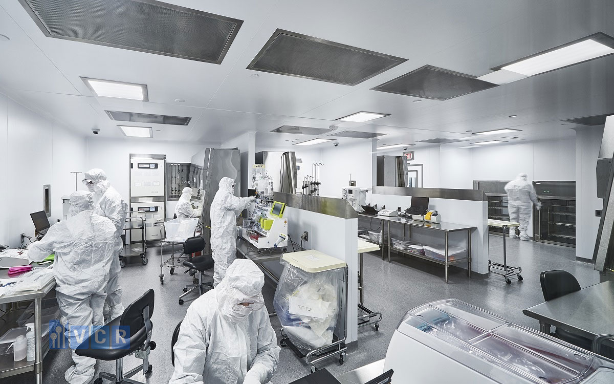
Room temperature should be defined according to product stability, process requirements, equipment heat load, and operator comfort. Not every cleanroom needs to operate at the same temperature.
Some materials may soften, crystallize, degrade, or become unstable when temperature increases. Excessively low temperatures may create condensation when materials or equipment are transferred from warmer areas.
Relative humidity is especially important for hygroscopic materials, effervescent products, dry powders, certain food products, and electronic components.
High humidity can cause powder agglomeration, reduced flowability, microbiological growth, packaging problems, or changes in product properties.
Very low humidity can create static electricity, dry surfaces, operator discomfort, and electrostatic discharge risks. The target humidity should therefore be based on process needs rather than automatically choosing the lowest achievable value.
Outdoor conditions vary by region and season. Northern Vietnam may experience highly humid periods, while southern Vietnam has a high latent load during much of the year.
HVAC systems must be sized using appropriate outdoor design data and worst-case operating conditions.
Air-change rate is the number of room air volumes supplied per hour. It is commonly used as a design reference but should not be treated as the only measure of performance.
A room may have a high air-change rate and still contain stagnant zones if supply and return outlets are poorly arranged. A well-organized airflow pattern may provide better contamination control with lower airflow.
Required supply airflow should be assessed from several demands: sensible heat removal, moisture control, particle control, exhaust-air replacement, ventilation, and pressure maintenance.
The highest resulting airflow requirement normally becomes the design basis.
Cleanroom classification is based on airborne particle concentration. However, a cleanliness class does not automatically prescribe one fixed air-change rate for every room.
The contamination load depends on personnel, clothing, process exposure, equipment, material movement, room recovery requirements, and airflow distribution efficiency.
HEPA stands for High-Efficiency Particulate Air. HEPA filters are commonly used where strict airborne particle control is required. Filter classification and installation arrangement should be selected according to the process and applicable standards.
Supply-air and return-air outlets must be arranged to sweep critical areas and minimize stagnant zones.
Return grilles should not be positioned too close to supply diffusers because this may create short-circuit airflow, where clean supply air returns to the system without adequately diluting contaminants in the room.
In dust-generating rooms, low-level return or extract grilles may improve dust capture, especially where heavier particles settle toward the floor. The final arrangement should still be based on particle behavior, process location, and equipment layout.
Smoke visualization testing can be used to observe airflow direction, turbulence, and stagnant areas. CFD, or Computational Fluid Dynamics, may also support airflow analysis during design.
CFD is a useful engineering tool, but actual airflow performance must still be verified after installation.
9. Supply-Air, Return-Air, Exhaust, and Dust-Extraction Design
Supply, return, and exhaust systems should be designed as one integrated network. Changing airflow in one branch can affect pressure and airflow in other rooms.
Supply ductwork should be sized to control air velocity, static-pressure loss, noise, and balancing performance. Unnecessary bends should be minimized, while adequate access should be provided for dampers, test points, and maintenance openings.
Return-air ducts from different risk zones should not automatically be connected to a common system. Where they are combined, the decision should be supported by a risk assessment, filtration strategy, and compatible product grouping.
Air containing dust, odors, chemicals, or solvent vapors may require treatment before discharge. Treatment systems may include particulate filters, HEPA filters, activated carbon, scrubbers, or process-specific technologies.
Exhaust discharge points must be located away from outdoor-air intakes, windows, pedestrian areas, and occupied zones. Poor location can cause discharged contaminants to be drawn back into the facility.
Local dust-extraction systems must be calculated together with room HVAC. When an extraction fan removes a large volume of room air, sufficient make-up air must be supplied to maintain the required pressure.
Where extraction systems operate intermittently, the HVAC controls should adapt to different operating states. A room balanced only when all extraction equipment is running may lose pressure when one extraction device stops.
Duct leakage affects system efficiency and contamination control. Leakage from a clean supply duct reduces delivered airflow, while leakage into return or exhaust ductwork can draw uncontrolled air from ceiling voids or technical areas.
Noise and vibration should be controlled through appropriate air velocity, flexible connectors, vibration isolators, acoustic treatment, and fan selection.
Silencers increase static-pressure loss and should be evaluated for cleanliness, access, and compatibility with the process environment.
After installation, the system should undergo TAB, which stands for Testing, Adjusting and Balancing.
TAB verifies airflow at each supply, return, and exhaust point and adjusts dampers and fan settings so that each room meets the approved design values.
10. HVAC Control, Monitoring, and Alarm Systems
Modern HVAC systems require reliable control and monitoring, not only mechanical equipment. The control system maintains environmental conditions, detects deviations, and provides operating data.
BMS stands for Building Management System. It may monitor and control AHUs, chillers, fans, valves, dampers, temperatures, humidity, pressures, and other building services.
EMS stands for Environmental Monitoring System. In regulated facilities, the EMS may be used to record critical environmental parameters that directly affect product quality, such as room differential pressure, temperature, and humidity.
The responsibilities of the BMS and EMS should be clearly defined. Not every engineering signal needs to be treated as a quality-critical data point. However, parameters that directly affect product quality may need controlled data storage, audit trails, access control, and alarm management.
Variable-frequency drives can adjust fan speed according to demand. When filter resistance increases, fan speed may be raised to maintain airflow or static pressure. During low-demand periods, speed can be reduced to save energy.
PID stands for Proportional-Integral-Derivative control. A PID controller adjusts the output according to the difference between the measured value and the setpoint.
PID settings must be tuned carefully. A system that reacts too aggressively may cause continuous fan-speed or damper movement and produce pressure oscillation. A system that reacts too slowly may not maintain control when process conditions change.
Alarm systems should include high and low limits, time delays, and suitable priorities. Time delays help prevent nuisance alarms caused by short door openings, but they should not be so long that genuine loss of control is hidden.
Different alarms may require different responses. A fan failure, low room pressure, high humidity, filter blockage, or sensor fault should not necessarily have the same alarm priority.
Data should be stored for a sufficient period to support deviation investigations, trend analysis, maintenance, and audits.
The system should include appropriate user access levels, time synchronization, change history, and data protection.
The project must also define the response to power failure. UPS stands for Uninterruptible Power Supply. It is commonly used for controllers, HMIs, data loggers, and communication equipment during short interruptions.
Large HVAC fans normally require a generator or another emergency power source if continued operation is necessary.
Restart sequencing is critical. Supply fans, return fans, exhaust fans, dampers, chilled-water valves, and process extraction systems should restart in a controlled order.
An uncontrolled restart may create abnormal room pressures or pull contaminants into adjacent spaces.
11. HVAC Testing, Commissioning, and Qualification
After installation, the HVAC system must be tested and demonstrated to meet the approved design requirements.
Commissioning is the structured process of verifying that the system has been installed, adjusted, and made operational according to the design intent.
Qualification is commonly applied in regulated industries such as pharmaceutical manufacturing. It usually includes Installation Qualification, Operational Qualification, and Performance Qualification.
Typical testing includes supply-air volume measurement, return and exhaust measurement, calculation of air-change rate, room pressure verification, temperature and humidity mapping, particle counting, airflow visualization, and recovery testing.
HEPA filter leak testing identifies leaks in the filter media, frame, gasket, seal, or installation.
Achieving a required room cleanliness classification does not automatically prove that the HEPA filter installation is leak-free.
Smoke testing is used to observe airflow direction, turbulence, airflow sweeping, and contamination pathways. Critical tests should be documented by clear video and conducted under defined operating conditions.
A recovery test measures how quickly the room returns to the required particle concentration after a controlled contamination challenge.
The test provides useful information about air-cleaning effectiveness and airflow distribution.
Alarms for pressure, temperature, humidity, fan failure, sensor fault, and filter blockage should be verified through controlled simulation or signal forcing.
Equipment should not be damaged merely to demonstrate an alarm function.
All instruments used for testing and qualification must have valid calibration status. Test locations, methods, operating conditions, and acceptance criteria should be defined in an approved protocol before testing begins.
Handover documentation should include approved as-built drawings, schematics, equipment schedules, material certificates where required, operation manuals, TAB reports, HEPA leak-test results, calibration certificates, commissioning records, and qualification reports.
12. Common HVAC Design Errors in Multi-Product Facilities
One of the most common mistakes is using one AHU for several production areas simply because the rooms are located close together. Physical proximity is not sufficient evidence that the rooms are compatible.
Another error is using return air without evaluating cross-contamination risk. Standard particulate filtration may remove particles but may not remove vapors, odors, gases, or molecular contaminants.
Some projects calculate airflow only from room area or volume. This ignores heat load, moisture load, process exhaust, personnel, dust generation, and pressure-control requirements.
Failing to calculate the rainy-season latent load is another frequent problem. The system may perform well during dry weather but fail to maintain humidity during periods of high outdoor moisture.
Selecting a fan with insufficient static pressure results in inadequate airflow after installation. Selecting a fan that is excessively large without suitable speed control can increase noise, energy use, and balancing difficulties.
No allowance for dirty-filter resistance means system performance gradually declines during operation. If the fan already runs at maximum speed with new filters, it has no capacity to compensate for increasing pressure drop.
Poor supply and return-air placement can create stagnant areas or short-circuit airflow. Large equipment may also block return airflow and prevent effective room sweeping.
Differential pressure sensors installed close to doors or supply diffusers may provide unstable and unrepresentative readings. Temperature sensors near heat sources or cooling outlets can also cause incorrect control responses.
Air Showers, Passbox, Dynamic Passboxes, Dispensing Booths, and dust-extraction equipment are often added after the central HVAC design is completed.
These devices can change airflow and room pressure and should therefore be included in the air-balance calculation from the beginning.
Some designs do not define product-changeover operating modes. During cleaning, fan shutdown, filter replacement, or maintenance, the intended airflow direction may be lost and residual dust may spread.
Excessive complexity is another risk. Too many sensors, motorized dampers, operating modes, and control loops can create a system that is difficult to understand, maintain, and qualify.
A good system should provide sufficient control without introducing unnecessary technical complexity.
13. Criteria for Selecting a Cleanroom Equipment Supplier
Cleanroom equipment directly interacts with the HVAC system. A supplier should therefore understand not only product dimensions and pricing, but also how the equipment affects airflow, pressure, filtration, containment, and room balance.
The supplier should be able to review cleanroom layouts, HVAC drawings, and pressure-cascade diagrams.
When receiving an inquiry for an Air Shower, Passbox, Dynamic Passbox, or Dispensing Booth, the supplier should evaluate the installation location, room classification, pressure on both sides, airflow requirement, and operating sequence.
The ability to coordinate with MEP contractors and cleanroom contractors is essential.
Electrical requirements, control signals, interlocks, extraction airflow, duct connections, heat loads, and wall-opening dimensions should be provided early enough for effective coordination.
Equipment should be supplied with technical drawings, material specifications, installation requirements, operating instructions, and testing documents.
Customized equipment should be manufactured only after approved technical drawings and interface details have been confirmed.
Equipment such as Air Showers, Dynamic Passboxes, Dispensing Booths, Sampling Booths, LAF units, FFUs, and HEPA Boxes may include their own fans, HEPA filters, controls, and alarms. Their interaction with the central HVAC system must therefore be evaluated.
Cleanroom doors and interlock systems affect room airtightness and pressure stability.
Differential pressure gauges and transmitters should have suitable measuring ranges, adequate resolution, and correctly installed pressure ports.
Vietnam Cleanroom Equipment supplies cleanroom equipment to cleanroom contractors, MEP contractors, and project owners.
During the equipment-selection process, Vietnam Cleanroom Equipment can support drawing review, technical clarification, equipment sizing, and coordination of HVAC interface requirements.
The equipment supplier does not replace the HVAC consultant or system designer. However, early technical coordination helps prevent common site problems such as incorrect wall openings, insufficient electrical power, missing duct connections, incompatible control signals, or equipment that disturbs the approved pressure balance.
14. FAQ: HVAC Design for Multi-Product Manufacturing Facilities
- Can a multi-product facility use one AHU for several production rooms?
Yes, one AHU may serve several rooms when the product risks, temperature, humidity, cleanliness classification, operating schedule, and return-air strategy are compatible. The decision should be based on risk assessment and not solely on room proximity or cleanliness grade.
- When should an HVAC system use 100% fresh air?
A 100% fresh-air system may be required when return air could carry toxic dust, allergens, active compounds, solvent vapors, strong odors, or other contaminants to different areas. The final decision should consider contamination risk, energy demand, environmental treatment, and process requirements.
- Should a dust-generating production room be positive or negative?
A dust-generating room is commonly maintained at negative pressure relative to adjacent areas to prevent dust escape. Where the product also requires environmental protection, an airlock, localized clean-air zone, or dispensing booth can be used to achieve both product protection and containment.
- Can two rooms with the same cleanroom classification share return air?
Not necessarily. Two rooms with the same ISO Class may manufacture incompatible products or present different contamination risks. Shared return air should only be used after evaluating product characteristics, process exposure, filtration capability, cleaning strategy, and containment requirements.
- How is the air-change rate determined for a multi-product facility?
The air-change rate is determined from particle-control requirements, heat load, moisture load, personnel, process exhaust, pressure balance, and recovery needs. A single standard value should not be applied to every room. Final performance should be confirmed through commissioning and qualification.
- Is HEPA filtration mandatory for every production area?
No. HEPA filtration is not automatically required in every manufacturing room. The required filtration level depends on product risk, cleanroom classification, process exposure, regulatory requirements, and environmental-control objectives.
- What parameters should be tested during HVAC acceptance?
Typical parameters include airflow, air-change rate, room pressure differential, temperature, humidity, particle concentration, HEPA filter leakage, airflow direction, and recovery time. Alarms, interlocks, emergency modes, and data-recording functions should also be tested.
- How does cleanroom equipment affect room pressure balance?
Equipment containing supply fans, exhaust fans, extraction systems, or frequently opening doors changes the room air balance. Air Showers, Dynamic Passboxes, Dispensing Booths, and dust collectors should be included in the HVAC airflow calculations to prevent pressure loss or airflow reversal.
15. Conclusion
HVAC system design for a multi-product manufacturing facility must be based on risk assessment, product characteristics, production processes, facility layout, zoning strategy, and actual operating conditions.
The design should not be determined only by room size, air-change rate, or cleanroom classification.
A suitable system must control cross-contamination, maintain stable temperature, humidity, cleanliness, and room pressure, and support cleaning, maintenance, monitoring, commissioning, and qualification.
Early coordination between the project owner, HVAC consultant, MEP contractor, cleanroom contractor, validation team, and equipment supplier can significantly reduce design conflicts and site modifications.
Vietnam Cleanroom Equipment supplies Air Showers, Passboxes, Dynamic Passboxes, Dispensing Booths, Sampling Booths, LAF units, FFUs, HEPA Boxes, differential pressure gauges, interlock systems, and other equipment for cleanroom contractors and controlled-environment projects.
Contact Vietnam Cleanroom Equipment for support in selecting equipment configurations, technical specifications, and cleanroom solutions suitable for your HVAC system, cleanroom layout, cleanliness classification, production process, and operating requirements.
Fast Delivery - On-Time Commitment - Dedicated Support
Hotline: 090.123.9008 - Call/Zalo 24/7
Email: [email protected]
Website: vietnamcleanroom.com
- Northern Office: 9/675 Lac Long Quan Street, Tay Ho Ward, Hanoi
- Southern Office: 15/42 Phan Huy Ich Street, Hiep Binh Ward, Ho Chi Minh City