




How Equipment Layout Affects Particle Distribution in Cleanrooms: Analysis of Machinery Arrangement and Recirculation Zones
Equipment layout directly affects airflow patterns and particle distribution in a cleanroom. An unsuitable arrangement can create recirculation zones, stagnant-air areas and local particle hotspots, even when the airflow volume and air-change rate still meet the design requirements.
- Why Can Equipment Layout Change Cleanroom Performance?
- How Are Particles Generated and Distributed in a Cleanroom?
- How Does Equipment Change the Airflow Path?
- Recirculation Zones, Stagnant-Air Areas and Dead Zones in Cleanrooms
- How Do Supply-Air and Return-Air Locations Affect Particle Control?
- How Do Heat, Vibration and Local Air Jets from Machinery Affect Particle Distribution?
- Equipment Layout in Non-Unidirectional Cleanrooms
- Equipment Layout in Unidirectional-Airflow Areas
- How Should Equipment Clearance and Orientation Be Determined?
- Interaction Between Personnel, Operations and Equipment Layout
- Methods for Evaluating Recirculation Zones and Particle Distribution
- Common Equipment-Layout Mistakes in Cleanrooms
- Principles for Optimizing Equipment Layout to Reduce Particle Accumulation
- When Should the Cleanroom Be Reassessed After a Layout Change?
- FAQ: Equipment Layout and Particle Distribution
- Conclusion
Why Can Equipment Layout Change Cleanroom Performance?
When a cleanroom is designed, parameters such as filtration efficiency, airflow volume, air-change rate, temperature, humidity and pressure differentials are usually clearly defined. However, one factor that can significantly affect particle control, but is sometimes insufficiently evaluated, is the arrangement of production equipment.
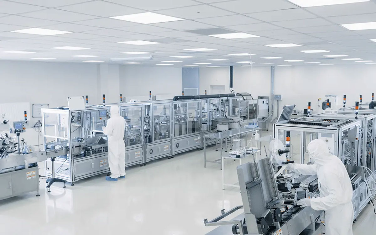
Machines do not merely occupy floor space. Every item of equipment becomes an obstruction in the airflow path. Its dimensions, height, geometry, installation position, heat output and mechanical movement can cause airflow to change direction, accelerate, decelerate or form local recirculation patterns.
As a result, a cleanroom with a properly designed air-handling system may still contain areas with higher particle concentrations if the equipment layout is unsuitable.
This explains why two cleanrooms with the same floor area, air-change rate and filtration system may produce different particle-distribution results. The difference may result from the position of the machinery relative to supply-air outlets, return-air grilles, doors, personnel routes and working zones.
If equipment blocks the main airflow, a low-velocity region may form behind the machine. If two machines are installed too close together, the narrow gap between them may create a high-velocity air stream while the downstream area develops stagnant or recirculating airflow.
If equipment produces a large amount of heat, upward thermal convection may oppose downward airflow supplied from the ceiling. These effects may not be visible in total airflow or average air-change-rate measurements. A room may meet its overall design parameters while still containing local particle hotspots.
Equipment-layout assessment should therefore not focus only on installation area, operational clearance and maintenance access. It should also consider aerodynamic behaviour, particle-generation sources, contamination transport routes and the ability of the ventilation system to remove contaminants.
How Are Particles Generated and Distributed in a Cleanroom?
Particles in a cleanroom can originate from many sources. Personnel are commonly one of the largest sources because of skin flakes, hair, garment fibres, movement and working activities.
Machinery, raw materials, packaging components, tools, door opening, maintenance and cleaning activities can also generate particles. Production equipment may release particles through mechanical friction, conveyor movement, gears, belts, packaging mechanisms, motors, insulation materials and component wear.
Some machines may not generate large quantities of new particles but can resuspend particles that have already settled on surfaces. Vibration, mechanical movement and cooling-fan airflow can return deposited particles to the air.
Once generated, particles may settle on surfaces, remain suspended or be transported to another area by the airflow. Larger particles generally settle more rapidly because of gravity. Smaller particles may remain airborne for longer periods and are more easily carried by air currents. However, actual particle behaviour also depends on shape, density, surface charge, humidity and air velocity.
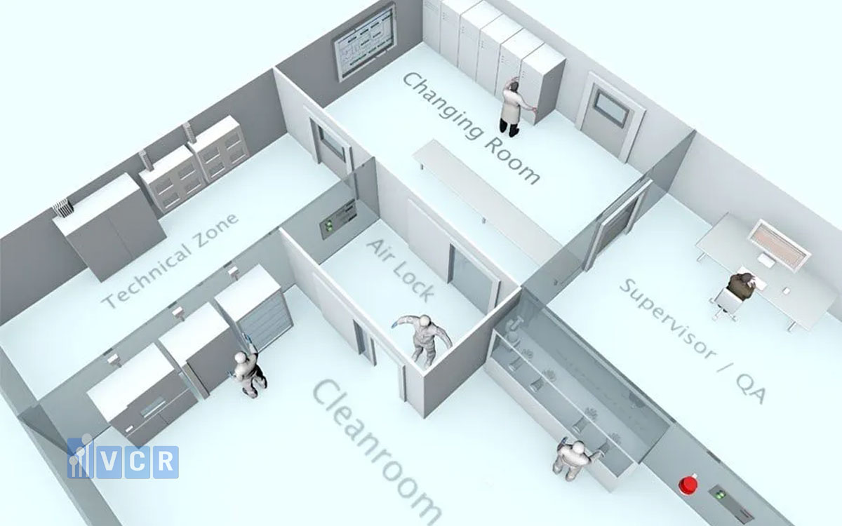
The objective in a cleanroom is not necessarily to remove every particle immediately after it is generated. The more important objective is to control the source, transport direction and residence time of particles within risk-sensitive areas.
When airflow is well organized, particles are diluted and transported toward return-air or exhaust-air points. When airflow is obstructed, particles may remain in the room for longer periods or be transported toward exposed products. Particle distribution is therefore not completely uniform throughout a cleanroom. Concentrations may be higher near a particle source, lower in well-swept areas and gradually accumulate in stagnant or recirculating zones.
Measurements taken at selected representative points reflect only the conditions at those locations and times. If the monitoring program does not cover high-risk zones, localized particle accumulation may remain undetected.
How Does Equipment Change the Airflow Path?
When airflow reaches a machine, it cannot continue along its original straight path. Air must move over, around or underneath the equipment. At the front surface of the machine, air velocity may decrease because of the obstruction. Along both sides, the airflow may accelerate because the available flow area becomes narrower.
Read more: Airflow in cleanroom: Laminar flow and Turbulent flow
After passing around the equipment, the airflow may separate from the surface and form a recirculation zone behind the machine. This behaviour is similar to airflow around an obstruction in a duct or an open space. In a cleanroom, however, the consequence is not limited to a change in velocity.
A recirculation zone behind the equipment may retain particles, chemical vapours or microorganisms released during manufacturing operations. The larger the equipment is in relation to the room, the more significant its influence is likely to be. A machine installed close to the ceiling may substantially obstruct downward supply airflow. A long production line may divide the cleanroom into two different aerodynamic zones.
Equipment geometry is also important. Machines with smooth, rounded surfaces generally create less severe airflow separation than machines with sharp corners, deep recesses or projecting components.
Large horizontal surfaces may obstruct downward airflow and provide locations for particle deposition. Shelves, cable trays, screens, lights, electrical cabinets and pipes installed above the working area can also interfere with the intended airflow.
The distance between equipment and walls directly affects air circulation. If the gap is too narrow, airflow may be restricted and the area may become stagnant. If the gap is wide enough for some airflow but too narrow for effective cleaning, it may become a long-term particle-accumulation zone. In some cases, a narrow space between the machine and the wall increases local air velocity. However, high velocity in the gap does not mean that the entire surrounding area is effectively cleaned.
Recirculation may still occur behind an obstruction or where the airflow passage suddenly expands. Equipment layout should therefore be evaluated according to the full airflow path from the supply outlet to the return-air grille, rather than merely confirming that some air can pass around the machine.
Recirculation Zones, Stagnant-Air Areas and Dead Zones in Cleanrooms
A recirculation zone is an area where the airflow does not continue in the main direction but instead rotates or circulates locally. A stagnant-air area is a region with very low air velocity and poor contaminant dilution and removal. A dead zone generally describes an area that receives little or no effective sweeping from the main airflow.
These terms are related but not identical. Air continues to move inside a recirculation zone, but the movement is mainly local and circular. In a stagnant-air area, the velocity is low and air exchange with the rest of the room occurs slowly.
Such zones commonly develop behind large machines, underneath equipment, between machinery and walls, in room corners, above tall cabinets or in spaces between closely positioned machines.
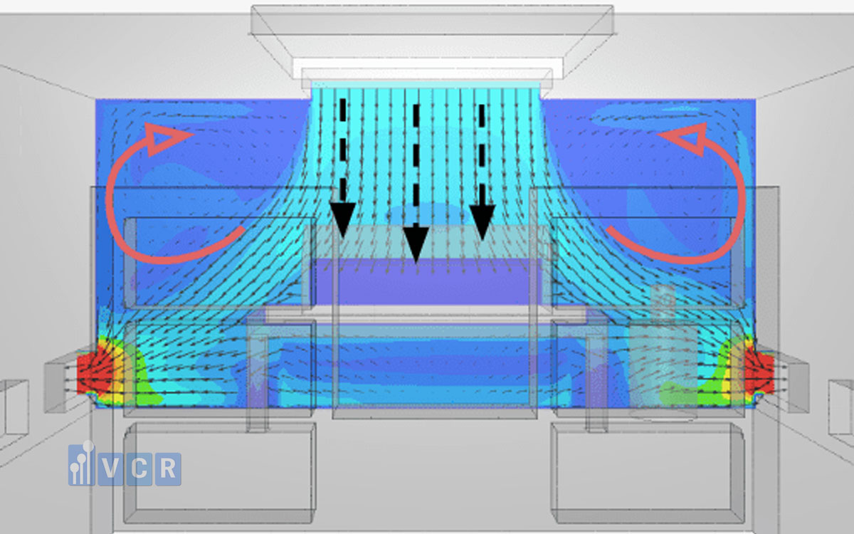
When particles enter a recirculation zone, they may not be immediately transported toward the return-air system. They may circulate locally, collide with surfaces or settle. When personnel pass through the area, doors open, machinery vibrates or fan conditions change, deposited particles may become airborne again. This helps explain why some locations experience intermittent particle alarms. Under stable conditions, particles may accumulate on surfaces or remain trapped within a recirculation zone. When a disturbance occurs, a short-term particle release can create a concentration spike.
Recirculation zones may also increase microbiological contamination risk when they are difficult to clean or contain moisture or product residues. Particles carrying microorganisms may remain in these zones longer than they would in areas with effective airflow sweeping.
In non-unidirectional cleanrooms, completely eliminating every recirculation region may be difficult. The practical objective is to limit their size, reduce particle residence time and ensure that high-risk areas remain controlled.
In unidirectional-airflow zones, the requirement is stricter. Air should move consistently through the critical area. A recirculation zone directly above or downstream of an exposed product may compromise the intended protection.
How Do Supply-Air and Return-Air Locations Affect Particle Control?
Supply-air outlets introduce filtered air into the cleanroom, while return-air or exhaust-air grilles provide a path for air carrying contaminants to leave the room. Particle-control effectiveness depends on how air travels between these points.
If a large machine is positioned directly below a supply-air outlet, the machine surface may deflect the airflow. Instead of reaching the intended working zone, the air may spread sideways or generate recirculation below the equipment edges.
If machinery blocks part of a return-air grille, extraction effectiveness in that area will decrease. Particles may remain in front of or beside the machine rather than being removed from the room.
Another concern is airflow short-circuiting. This occurs when air travels directly from a supply outlet to a nearby return grille without sweeping the manufacturing area or passing through the main particle-generation zones.
The total room airflow may still meet the design value even though cleaning effectiveness in the production area is poor.
- Low-level return-air grilles can assist in removing particles and warm air after supply air has moved downward from the ceiling. However, their effectiveness may be greatly reduced when they are blocked by machinery or located inside a recess behind a production line.
- High-level returns may be suitable for certain designs, but they can allow recently supplied clean air to return to the system before passing through the working zone.
There is no universal clearance distance that applies to every machine and return-air grille.
The required distance depends on equipment dimensions, airflow volume, airflow direction, heat load and the intended contamination-control objective.
During the design phase, return-air locations should be positioned to capture contaminants from known sources. Dust-generating or heat-producing equipment should be arranged so that contaminated airflow does not pass across clean products before reaching the return or exhaust point. After installation, the actual airflow path should be confirmed by airflow-visualization studies, velocity measurements and particle data.
How Do Heat, Vibration and Local Air Jets from Machinery Affect Particle Distribution?
Heat generated by motors, electrical cabinets, heating devices and packaging equipment creates convection currents within the room. Warm air rises. If the room is designed with downward airflow from the ceiling, upward thermal convection may oppose the main supply airflow.
Where the two air streams interact above a heat-producing machine, recirculation may develop. Particles released from the equipment or deposited on its surfaces may be carried upward and distributed to other parts of the cleanroom.
Cooling fans installed inside machinery are another important consideration. Some machines draw air from below and discharge it behind the equipment. Others blow air horizontally across electrical cabinets or motors.
If the discharge direction opposes the room airflow, the local jet can disrupt the intended airflow pattern.
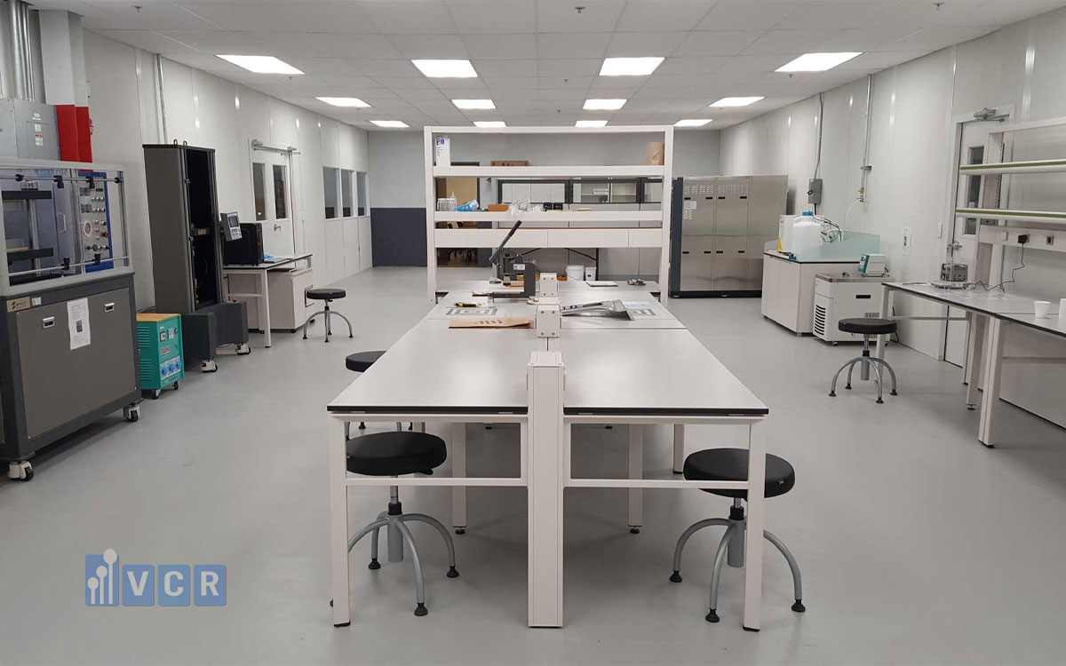
Air discharged by an equipment cooling fan may not be filtered to the same level as the cleanroom supply air. If the fan draws air from an area where dust has accumulated, it may become a particle-dispersion source.
Vibration from motors, presses, compressors, conveyors and rotating mechanisms can resuspend particles deposited on equipment surfaces.
Machines with continuous moving parts also create local turbulence. Opening and closing equipment doors, robotic-arm movement, bottles moving along conveyors and packaging materials sliding across surfaces can all generate localized airflow disturbances.
During layout assessment, information should be collected on heat output, exhaust direction, cooling-fan locations and moving components. Evaluating only the static external geometry of the machine is not sufficient.
In some projects, the equipment layout is approved while the machinery is not operating. Once the production line starts, heat and movement can significantly change the airflow pattern.
Evaluation under operational conditions is therefore more meaningful for identifying actual risks.
Equipment Layout in Non-Unidirectional Cleanrooms
Many ISO Class 7, ISO Class 8, Grade C and Grade D cleanrooms use a non-unidirectional dilution-airflow principle.
Cleanroom Standard Classifications
Filtered air enters the room, mixes with the existing air and gradually reduces particle concentration before being returned to the air-handling system. In this type of system, air-change rate is an important parameter, but it does not fully describe distribution effectiveness. If the air does not mix evenly or if part of the room is shielded by equipment, particle concentration at some locations may be higher than the room average.
A large machine positioned in the middle of a room can divide the supply airflow into multiple paths. The area in front of the machine may be well swept, while the downstream area may have low velocity.
A long production line installed perpendicular to the dominant airflow direction can create an aerodynamic barrier. If return-air grilles are located only on one side, contaminants on the opposite side of the line may not be effectively removed.
Machines installed too close to walls reduce air-circulation space and make cleaning more difficult. If heat-producing components or exhaust fans are located behind the machine, this space can become a concentrated heat and particle zone.
Equipment with numerous horizontal surfaces also provides additional particle-deposition areas. Cabinet tops, machine covers, supports and overhead pipes should be designed and arranged to allow effective cleaning.
In a non-unidirectional cleanroom, sufficient clearance should be provided for air to move around the machinery and return to the air-handling system. However, this clearance must also support operation, maintenance and cleaning.
Equipment should not be added to a room merely because floor space appears available. A high equipment density reduces free air volume, increases heat load, creates more obstructions and may cause the HVAC system to operate outside its original design conditions.
When new machinery is added, the heat load, airflow volume, pressure differentials, recovery time and particle distribution should be reassessed.
Equipment Layout in Unidirectional-Airflow Areas
In a unidirectional-airflow area, filtered air moves in a relatively uniform direction through the critical zone to protect exposed products or product-contact surfaces. The fundamental principle is that clean air should reach the product and critical surfaces before passing over personnel, materials or potentially contaminated equipment components.
Any obstruction positioned above an exposed product may reduce the level of protection. Screens, lights, sensors, brackets, pipes and operator hands should be arranged so that they do not obstruct the clean airflow.
When downward airflow meets a large horizontal surface, it spreads sideways. A low-velocity or reverse-flow zone may develop beneath that surface.
If the product is located within this area, the protective airflow may no longer be stable.
Personnel are also airflow obstructions. If an operator stands upstream of the product, the airflow may pass over the operator’s body, hands or garments before reaching the critical area.
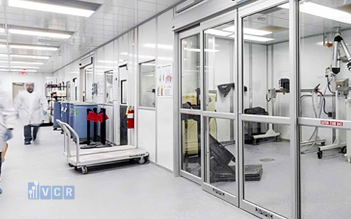
The equipment layout should allow personnel to work from the downstream side or from the position least likely to interfere with protective airflow.
In a unidirectional-airflow unit, the distance between the filter and the working zone should allow the airflow to stabilize while avoiding excessive distance that allows additional obstacles to interfere with it.
Air-velocity measurements taken at only a few points are not sufficient to prove that the entire work zone is protected. Airflow direction, uniformity and behaviour during operations must also be considered.
Smoke studies should include unfavourable but realistic activities such as introducing materials, removing products, opening equipment doors, adjusting machinery, clearing jams and performing manual interventions.
A layout that performs acceptably at rest but develops recirculation during actual operation cannot be considered fully suitable.
How Should Equipment Clearance and Orientation Be Determined?
The distance between machinery and walls, ceilings and adjacent equipment should meet three requirements at the same time: airflow circulation, cleaning access and maintenance access.
If the clearance is too small, air movement is restricted and personnel cannot clean the area effectively. If the clearance is large enough to create a hidden passage behind the machine but the area is rarely accessed, it may still be neglected during routine operation.
The orientation of a machine relative to the airflow is also important. A long machine installed parallel to the main airflow may create less obstruction than the same machine positioned perpendicular to it. However, this also depends on the locations of the supply and return-air outlets. Machine geometry cannot be evaluated separately from the overall room airflow pattern.
When several machines are installed in a row, the spaces between them should be sufficient to avoid narrow, inaccessible gaps. When machines face each other, the design should consider equipment exhaust direction, door-opening paths and operator positions.
A staggered arrangement may reduce the chance that two machines block the same airflow path, but it can also create more complex recirculation patterns.
Components that require frequent maintenance should not be located directly against a wall or behind another machine. Maintenance in an inaccessible area can generate contamination and make post-maintenance cleaning more difficult.
The clearance above machinery must also be considered. Very tall machines may be positioned close to terminal filters or supply outlets, causing the airflow to be obstructed before it can distribute properly.
There is no single clearance value that is appropriate for every cleanroom. The required space should be determined through engineering assessment, layout drawings, simulation where appropriate and actual field testing.
Interaction Between Personnel, Operations and Equipment Layout
Equipment layout determines how personnel move and work inside a cleanroom. If walkways are too narrow, personnel are more likely to contact machines, walls, carts or other operators. Each movement and contact can increase particle release.
If the operating position is located on the opposite side of the material supply, personnel may need to walk around the machine repeatedly. Increased movement raises the particle load and increases the likelihood of disturbing airflow.
If a personnel route crosses a sampling location or exposed-product zone, employee movement can create localized particle peaks.
Worktables, chairs, carts and material containers are often added after the main machinery layout has been finalized. These items are also airflow obstructions and must be included in the assessment.
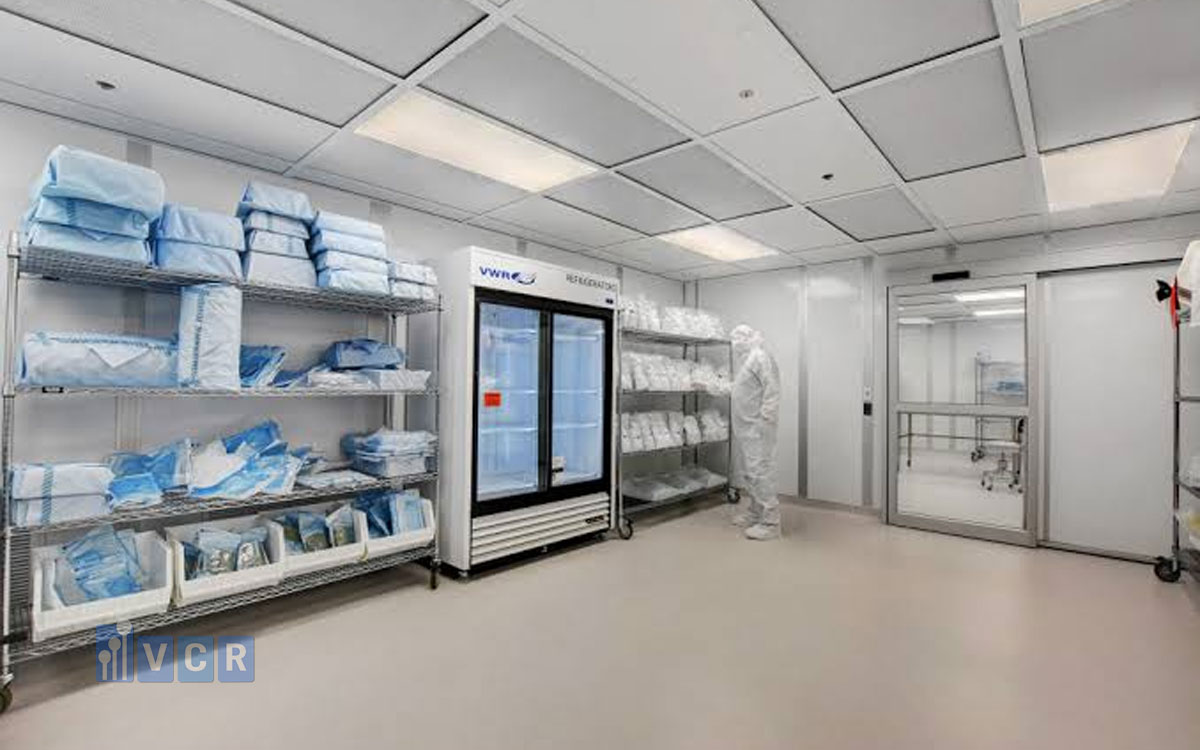
A temporary cart placed beneath a supply-air outlet can affect airflow in the same way as fixed equipment. Materials stacked too high on the cart may also block the airflow.
A good layout should reduce the number of times personnel pass through critical zones, minimize crossings between clean materials and waste, and provide convenient working positions without placing the operator upstream of the exposed product.
Layout assessment cannot therefore be performed only on a drawing showing fixed machinery. It should also simulate personnel, materials, tools, carts, open doors and actual operating activities.
Methods for Evaluating Recirculation Zones and Particle Distribution
No single method can fully assess the influence of equipment layout. An effective approach usually combines airflow visualization, velocity measurements, particle measurements and operational assessment.
Airflow-visualization testing uses smoke or a suitable fog to show the direction of air movement. The study can identify blocked airflow, recirculation zones, reverse flow and airflow short-circuiting from supply outlets to return-air grilles.
The test scenario should reflect operational conditions rather than only at-rest conditions. Machinery should operate, personnel should perform representative tasks and doors should open according to normal procedures.
Air-velocity measurements at multiple locations help quantify areas with low velocity or high variation. Measurements should be taken in front of, beside, behind and above machinery rather than only at the supply outlet.
Particle mapping can identify concentration differences between locations. Measurements may be taken at different heights to assess the breathing zone, working zone and areas near the floor.
Data should be collected in both at-rest and operational states. Measurements performed only when the room is empty and the machinery is stopped will not reflect many actual particle sources and airflow disturbances.
When the equipment layout is changed, before-and-after data should be compared. This helps determine whether the modification improves or reduces contamination-control performance.
Computational Fluid Dynamics, commonly abbreviated as CFD, can be used to predict air velocity, airflow direction, temperature distribution and recirculation zones.
CFD is especially useful during the design phase, before equipment is installed. Different layout options can be compared before construction or installation begins. However, simulation results depend heavily on the quality of the input data. If machine dimensions, heat loads, fan directions, airflow rates or boundary conditions are inaccurate, the model may not reflect actual conditions.
CFD should not completely replace post-installation testing. A suitable approach is to use simulation to guide the design and then confirm performance through field measurements and airflow studies.
Common Equipment-Layout Mistakes in Cleanrooms
A common mistake is placing large equipment directly below a supply-air outlet without evaluating its effect on airflow distribution. Another mistake is placing cabinets, storage racks or machines too close to return-air grilles, reducing extraction area and creating particle accumulation in front of the obstruction.
Installing machines directly against walls to save space often creates difficulties for cleaning, maintenance and airflow circulation. Many facilities add new equipment without reassessing the HVAC system. The new machinery may increase heat load, create additional particles and alter the airflow path.
Some designs rely mainly on the average air-change rate. If the total value meets the requirement, the room is considered acceptable without checking the distribution at individual locations.
Sensor and sampling-probe positions may also be selected for installation convenience rather than risk relevance. The resulting data may not represent the area with the highest particle concentration.
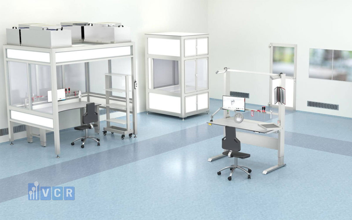
After a layout change, smoke studies may not be repeated or may be performed only in the at-rest state. This can fail to identify recirculation that develops when the machinery is operating.
Another mistake is evaluating the average particle concentration of the room while ignoring individual sampling locations. Some points may repeatedly alarm even though the overall average remains acceptable.
Particle data should therefore be analysed according to location, time, operating state and activity.
Principles for Optimizing Equipment Layout to Reduce Particle Accumulation
Layout optimization should begin with the exposed-product area or the process step with the highest contamination risk. The intended airflow direction, particle sources and return-air path should be identified before equipment positions are finalized.
The path from the supply outlets to the return-air grilles should remain as unobstructed as practicable. Large machines should not completely block the main airflow route. Obstructions above exposed products and critical surfaces should be minimized. Sensors, screens and supports should be positioned outside the primary protective airflow whenever possible.
Particle-generating equipment should be positioned near an appropriate return or exhaust path so that particles can be removed before spreading into cleaner zones.
Heat-producing equipment and machines with exhaust fans should be arranged so that warm or contaminated air does not flow across the product.
Clearance around machinery should be sufficient for airflow, cleaning and maintenance. Narrow gaps that cannot be accessed should be avoided. Horizontal surfaces, enclosed recesses and difficult-to-clean corners should be minimized. Machine tops should be designed or positioned so that they can be cleaned periodically.
The machinery layout must be coordinated with personnel, material, tool and waste flows. Reducing unnecessary movement helps decrease particle release and cross-contamination risk.
Before final approval, the layout should be reviewed using three-dimensional drawings, CFD where appropriate and actual field testing after installation.
When Should the Cleanroom Be Reassessed After a Layout Change?
Any modification that can affect airflow or particle-generation sources should be reviewed through the change-control system. Typical examples include moving a large machine, replacing equipment with a different size, adding a production line, installing a worktable, cabinet, support frame or display screen.
Changes in personnel numbers, operating procedures, material-transfer direction and operator position can also affect particle distribution. If supply-air outlets, return-air grilles or fan airflow rates are modified, the existing equipment layout should be reassessed.
An increasing particle or microbiological trend at a particular location may also indicate the need to investigate recirculation and airflow-distribution performance. Post-change testing may include airflow visualization, velocity measurement, airflow-volume measurement, pressure-differential verification, recovery testing, particle measurement and cleanroom reclassification.
Not every change requires every test to be repeated. The test scope should be based on the risk assessment and the likely extent of the impact.
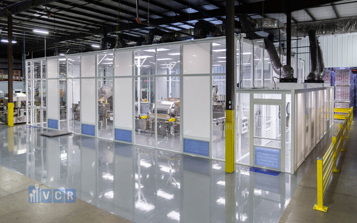
Read more: 5 factors you should pay attention on cleanroom design
FAQ: Equipment Layout and Particle Distribution
Does equipment positioned below a supply-air outlet affect cleanroom performance?
Yes. The equipment can obstruct or redirect supply air. Low-velocity areas, recirculation zones or sideways airflow may develop above, below or around the machine. The extent of the impact depends on machine dimensions, distance from the outlet, airflow type and product location. Airflow visualization and actual velocity measurements should be used to confirm performance.
Can machinery installed close to a wall create recirculation?
Yes. When the gap between the machine and the wall is too narrow, airflow is restricted and the space may become stagnant. Even if air passes through a narrow gap, a recirculation zone may still form downstream. Close wall clearance also creates difficulties for cleaning and maintenance.
Does a high air-change rate eliminate all stagnant-air zones?
No. Air-change rate indicates the total quantity of air supplied to a room over time, but it does not show whether that air is distributed uniformly. A cleanroom can have a high air-change rate and still contain stagnant areas when machinery blocks the airflow or supply and return locations are unsuitable.
How can a particle-accumulation zone be identified?
Airflow visualization, velocity measurement, particle mapping and trend analysis can be combined. Locations with repeatedly high particle counts, slow recovery or particle spikes when machinery operates may indicate accumulation. Surface cleanliness and deposited residue can also provide useful evidence.
Is a smoke study required after moving a machine?
When the relocation may affect the airflow pattern, the smoke study should be repeated or an engineering assessment should be performed to define the required test scope. This is particularly important in unidirectional-airflow areas and locations with exposed products.
How far should a return-air grille be from machinery?
There is no single distance suitable for every application. The required clearance depends on equipment dimensions, return-air volume, airflow direction, heat load and particle sources. Return grilles should remain unobstructed and should not be blocked by machinery, racks or stored materials.
Can heat-producing equipment increase airborne-particle concentration?
Heat-producing equipment does not necessarily generate large numbers of particles directly, but thermal convection can lift particles from equipment surfaces into the air. Heat may also change airflow direction, create recirculation and reduce particle-removal efficiency in certain areas.
Why can the average particle count pass while some locations repeatedly alarm?
An average value can hide local variation. Locations near particle sources, behind machinery or inside stagnant-air zones may have higher concentrations. Particle results should therefore be reviewed by individual location rather than only by the overall room average.
Can CFD replace actual cleanroom measurements?
It should not. CFD is useful for comparing design options and predicting recirculation, but its reliability depends on the accuracy of the input data. After installation, smoke studies, velocity measurements and particle testing under operational conditions are still required.
Does equipment layout affect cleanroom qualification results?
Yes. Equipment layout affects airflow velocity, airflow direction, recovery time and particle distribution. After a significant layout change, previous qualification results may no longer represent current conditions. The facility should determine the required requalification scope through a risk assessment.
Conclusion
Equipment layout is a technical factor that directly influences airflow paths, the formation of recirculation zones and the ability of a cleanroom to remove airborne particles.
A room may meet its designed airflow volume, air-change rate and filtration class without achieving uniform cleanliness throughout the space. Local particle hotspots may develop behind machines, in room corners, in narrow gaps or within shielded areas.
Machinery layout should therefore be assessed together with the HVAC design, supply and return-air positions, heat loads, particle sources and personnel movement.
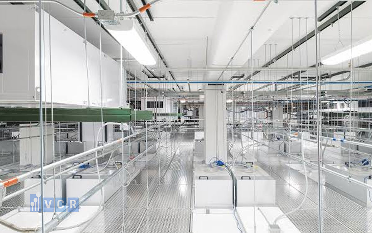
During the design phase, three-dimensional drawings and airflow simulation may be used to compare different arrangements. After installation, performance should be confirmed through airflow-visualization studies, velocity measurements and particle mapping under operational conditions.
When the layout is changed, the facility should not evaluate only whether the machinery physically fits into the available space. The impact on airflow, pressure, cleaning, maintenance and environmental monitoring should also be assessed.
A well-designed layout does more than make equipment operation convenient. It helps the cleanroom maintain a more stable state of control throughout its operating life.
Contact Vietnam Cleanroom Equipment for Technical Support
When designing or modifying a machinery layout, cleanroom contractors and project owners should evaluate airflow direction, supply and return-air locations, equipment clearance, heat load and the risk of recirculation-zone formation.
As a cleanroom equipment supplier supporting cleanroom contractors, Vietnam Cleanroom Equipment - VCR provides technical support in selecting high-efficiency particulate air filters, HEPA filter boxes, fan filter units, differential-pressure gauges, unidirectional-airflow equipment, pass boxes and other cleanroom accessories for different project requirements.
Selecting the correct equipment configuration and coordinating it with the machinery layout during the design stage can reduce modification risks, support qualification activities and minimize the formation of local particle-accumulation zones during operation.